Page 1 of 2
555+mosfet+ignition coil ignition
Posted: Mon Jul 13, 2009 3:52 am
by Copperboy
I've always wanted to build a simple and powerful ignition system, and I think I finally found it! At least it's powerful! As I not are that into electronics me and a friend sat down and researched, tried and built, and after many hours, blood sweat and tears (not tears

) this is what we came up with.
Essentially it's a pair of ignition coil run in anti parallel , switched from a 24V supply by a mosfet (irfp 260, later irfp 460) at around 200Hz. The sparks in the pictures was made with the irfp 260, pulling about 4amps from the battery (if i remember it correctly). The breakdown voltage of the mosfet is 200V, and I think the coils are 100:1 each, resulting in around 40kV at the business end. This is the circuit we originally built, but then we modded it a bit:
http://www.geocities.com/amptramp2002/amptramp001.htm
Mosfets tend to break from inductive kicks, this is why we put a capacitor over the mosfet, trying to slow the kicks down. This page shows numerous ways of protecting your mosfet:
http://www.saunalahti.fi/plahtee/youtub ... ition.html
The smell of ozone lay thick and my friends apartment went black from flying bits incinerated plastics.
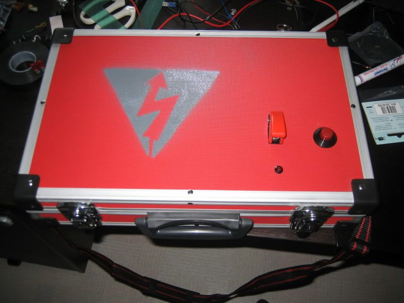
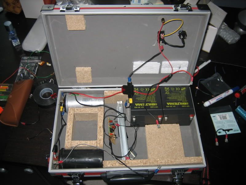
In a box:
http://i103.photobucket.com/albums/m128 ... G_1534.jpg
http://i103.photobucket.com/albums/m128 ... G_1535.jpg
We've also tried the irfp 460, and with a breakdown of 500V, the plasma arc created was about 10cm long, drawing 8amps. Scary! 8) I didn't get a chance to take any pictures before the mosfet called it a day though.
Enough talk, here's some pics from our first attempts with the irfp 260:
(as they are pretty big I think it easier linking to them)
http://www.saltaren.se/24V_Mayhem/24v_m ... 620_33.jpg
http://www.saltaren.se/24V_Mayhem/24v_m ... 0620_3.jpg
Shewing gum
http://www.saltaren.se/24V_Mayhem/24v_m ... 620_37.jpg
Poker mark
http://www.saltaren.se/24V_Mayhem/24v_m ... 620_39.jpg
Leaf
http://www.saltaren.se/24V_Mayhem/24v_m ... 620_41.jpg
http://www.saltaren.se/24V_Mayhem/24v_m ... 620_65.jpg
Just wanted to show it's not that difficult using IC's to solve your ignition problem. Tell me what you think!

Posted: Mon Jul 13, 2009 5:18 am
by inonickname
Hmm...
I do have an old ignition coil..but I don't have anything that warrants this (yet...)
People have competitions with GM coils, and have drawn up to 10" sparks if I recall..
Posted: Mon Jul 13, 2009 6:11 am
by rp181
Too bad you made it HUGE!!!
555+ mosfet in a flyback:
http://www.spudfiles.com/forums/viewtop ... 12e#251724
In about 6" cube. for short runs, like ignition, i can remove the sink and have it around 4" square.
If you want a compact, high power (more than above) get a flyback, and search ZVS flyback driver (Zero voltage switching)
Posted: Mon Jul 13, 2009 6:53 am
by jmadden91
rp181:
Your link goes to the same page mate

Posted: Mon Jul 13, 2009 7:01 am
by Hotwired
jmadden91 wrote:rp181:
Your link goes to the same page mate
Now that's embarrassing

Of course the huge space hog in all of this is the massive ignition coil.
Posted: Mon Jul 13, 2009 7:06 am
by Copperboy
Hmm, that link directs me here again..
Yeah, my box is pretty large, but if one want it more compact just use one coil and the driver, about as large as only the ignition coil and the battery. This was intended as a sort of "field box", not as an onboard ignition.
When using 12V and the irfp 260 the mosfet doesn't really get warm at all and it doesn't need any spike protecting either, thus making it pretty compact I would say. And you could run it for as long as you want.
I never really liked flybacks, mostly because it's hard obtaining one
and I think I'd mess upp the winding as well hehe.
The ZVS looks pretty tempting though!
I haven't looked into ZVS at all, does it suffer from inductive kicks?
Posted: Mon Jul 13, 2009 7:25 am
by Hotwired
Copperboy wrote:And you could run it for as long as you want.
That's a plus for reliability but all of one second would be pretty generous for ignition. If it took any longer you'd be worried ^^
Copperboy wrote:I never really liked flybacks, mostly because it's hard obtaining one
and I think I'd mess upp the winding as well hehe.
Slightly. I got mine from a TV someone had dumped ^^
After scraping off the cobwebs, slugs and critters then chasing out the spiders (one managed to cling on right up til the moment I physically took the flyback core apart)... it brushed up very nicely. Modern flybacks have a U shaped array of terminals on the base and once you have the circuit set up there's nothing you can really muck up.
Find the linked terminals with a continuity tester and switch the leads about to find the best coil, some work better than others.
If all you want is to put pulses of 12V in then a flyback will be as easy as an ignition coil. If actually driven as a flyback then you have to find two coils and get the polarity correct which is even more fun.
Posted: Mon Jul 13, 2009 9:42 am
by Copperboy
I actually have a flyback on the bench right next to me just waiting to be used, perhaps I should try feeding it some munchy square wave hehe. It got that U shaped array of terminals as well.
What's the primary secondary winding ratio on one of those?
Posted: Mon Jul 13, 2009 10:21 am
by Hotwired
In the realms of ignition coils.
Varies quite a bit, mine has more than a dozen terminals and maybe 4 different windings with some of the coils having various taps on them.
There is one particular coil in the whole array which has the best effect, it has no taps, on mine it is two terminals on the end of one of the legs of the U. I think it varies from manufacturer so that may not be worth much.
There is a return for the HV output in the U somewhere, if you hold the HV wire close while it's running you'll soon find the one it likes. May not be healthy for your circuit if you let the HV touch the input terminals for too long ^^
Posted: Mon Jul 13, 2009 10:58 am
by starman
Some pretty monsterous arcs you obtained there. Are you planning to incorporate this on a combustion or hybrid cannon project?
Posted: Mon Jul 13, 2009 1:04 pm
by Technician1002
My 2 cents worth are due. This a mostly in regards to the destroyed transistors and what ate them. Most non electronics spudders can skip the following. It's a little heavy on electronics theory.
The coil is an inductor. It resists changes in current. Changes in current either require applied voltage or an attempt at change makes voltage. The voltage is directly related to the rate of change.
Switching off a transistor feeding current to a coil will most certainly let out the magic smoke. The change is very abrupt and the resulting voltage is very high. As mentioned by the thread author, a common solution is to simply add a capacitor. now the current drops gradually while building a charge in the capacitor limiting the voltage. Proper selection of capacitor can keep the peak voltages manageable. The problem is that when you now turn the transistor back on with a cap with 200 volts on it, it again lets out the magic smoke from very high current. It seems like you can't win.
Looking at the coil and capacitor (ignoring the transistor for a minute) you have a parallel R/C circuit. It's a tuned circuit tuned to a particular frequency. Tuning the transistor to drive this circuit can turn on the transistor at the right time with low voltage on it, drive current into the coil, switch off, let the voltage peak and resonate back, and then pulse it again. You now have the basic circuit used in radio transmitters. Lots of output power, limited voltages and current to the transistor, etc.
In a non continuous mode, where individual sparks are desired such as in an ignition application, the dwell time (on time) of the transistor can be limited to limit the maximum current (energy) stored in the magnetic field. When turned off a single pulse is generated which can then be repeated after the damped wave dies down. With proper selection of components and dwell time, the voltages can be controlled within the limits of your transistors. Often an ignition coil runs with up to 400 volts peak on the primary.
Capacitive discharge ignition uses a high voltage to create a quick change of flux in the coil to generate the high output voltage pulse. CDI ignition typically deliver about 300 volts into the primary from a capacitor for a short duration pulse. This cap is a high frequency type very similar to the one used on the points in a conventional ignition. Electrolytics don't survive the repeated high current discharges due to the effective series resistance.
Sorry spudders, it's a lot of theory beyond the basics of spudding.
Posted: Tue Jul 14, 2009 1:04 am
by Copperboy
Very good lecture Technician1002! I've been tempted using an SCR to pulse the cap in the primary, seems quite sturdy.
As I'm not that into electronics, where's the tuned circuit? If there's not a cap over the coil, I think it look like some sort of filter

I think everyone could understand basic electronics! Just use howstuffworks.com hehe.
If one look at the datasheet for the mosfets, they have a certain energy they can tolerate after the zener in them lets go. If the cap is small enough, it shouldn't fry the mosfet. I use a 600V 100nF. Also one could help the mosfet avalanching (spelling?) with some TVS.
This circuit is said by its creator to have the dwell to 2/3 of a cycle, which is good for power but maybe a bit hard on the mosfet, hehe.
Starman;
Perhaps
At least now I have the posibility! At a 10x mix the sparklenght could be set at 5mm, assuming the spark is 50mm in the open. Have i got it right?
Posted: Tue Jul 14, 2009 1:24 am
by Technician1002
SCR's are used in CDI ignition. They have the advantage of a fairly fast turn on, and auto turn off when the polarity reverses and current drops to zero. A diode is frequently used to recharge the cap from the unused portion of the energy by dumping the ringing voltage back into the capacitor. Because the peak voltage is when the voltage is applied, the spark happens when the SCR is on. Over current from a shorted spark gap can destroy the SCR. CDI doesn't like shorts.
If you use an SCR to pulse the cap, remember a CDI discharges a high voltage into the primary to create the rapid flux change. Dumping a cap at 12 volts into the coil won't do much. Charging the small cap with a camera flash inverter may work well. Some people use the camera flash cap, but it's way too much energy to dump into the coil. You get a spark, but the coil goes into saturation wasting most of the energy. A .22 or so Mfd instead of 50 MFD works well.
As I'm not that into electronics, where's the tuned circuit?
I just took a look at the schematic you linked to. The cap is directly in parallel with the primary of the coil. The coil and 0.22 Mfd cap is a tuned circuit. The scope trace page even states it.
http://www.geocities.com/amptramp2002/amptramp003.htm
Resonance is an essential element of this unit's operation.
Since the coil has a condenser wired
across it, we have made a 'tuned circuit'
The "resonant circuit" is simply the ignition coil is the inductor and the cap is the one protecting the mosfet. When the transistor turns off, the current is provided by the inductance of the coil. As the capacitor charges, the flux rate increases. If there is no spark, the energy when the current drops to zero is all in the capacitor as voltage. The high voltage is forcing rapid flux change in the coil so voltage on the secondary is high at this point. The current reverses as the capacitor discharges. As the capacitor discharges, the current builds in the coil but in the reverse direction. At the peak negative voltage, the current again goes to zero with the charge in the capacitor. This process repeats. The frequency is determined by the value of the components in this parallel resonant circuit.
If a spark occurs, the charged cap (peak voltage on the cap and minimum coil current is peak output voltage) the cap provides power into the transformer to feed the load arc. This happens when the mosfet is off. Again a short can prevent flux from building causing high transistor current and may destroy the transistor. Avoid shorting the secondary. Let it spark and draw current at the voltage peak only. Current spike will be drawn from the cap, not the mosfet.
As far as duty cycle is concerned, for high rep rates, it's OK to use 2/3 duty cycle. The important thing to remember is the inductor resists change in current. With short on times, this keeps the current at safe levels. At low frequencies, the on time may be long enough to saturate the iron core. An increase in current does not increase the magnetic field strength and therefore the change in magnetic field no longer limits the current. Only the DC resistance now limits the current. This may be high enough to destroy the mosfet as the primary of the coil is just a few turns of wire.
At moderate rep rates, at 12 volts it takes time to build current in the coil and at 3-400 volts, very little time to drop the current, so 2/3 dwell duty cycle is fine. Keep the duration of the on time to under about 0.05 seconds if going for low rep rates. This is to limit dwell time.
In a old traditional points and condenser car ignition system, a resistor is used to limit this current.
Posted: Tue Jul 14, 2009 2:10 am
by Copperboy
Ah, then I see!
The battery!
In the original ignition coil wires there seems to be about 1kOhm resistance, and now I think I know why, thanks!
Yes, I've spend a lot of time on Powerlabs looking at his SCR circuits.
It seems like a relatively easy way of obtaining high voltage, I assume the cap can brutely rise the current in the primary faster than a shut off system can dump it. (thinking of the flux)
What are the CDI SCR rated to, and how is it charged and triggered? Grateful for answers!
Edit: (Sorry, seems like I didn't read your post entirely. But now I have! hehe)
Posted: Tue Jul 14, 2009 2:24 am
by Technician1002
Copperboy wrote:Ah, then I see!
The battery!
Yes, I've spend a lot of time on Powerlabs looking at his SCR circuits.
It seems like a relatively easy way of obtaining high voltage, I assume the cap can brutely rise the current in the primary faster than a shut off system can dump it. (thinking of the flux)
What are the CDI SCR rated to, and how is it charged and triggered? Grateful for answers!
Edit: (Sorry, seems like I didn't read your post entirely. But now I have! hehe)
CDI uses the same value cap as used before, but it is simply at the peak voltage, charged with a inverter. A timer, points, sensor, etc provides a narrow pulse to turn on the SCR. It must have a value of at least the peak voltage. 400 volt units are common. An advantage over mosfets is they don't have a clamping diode, so they permit the tuned circuit to swing negative and back positive. The positive swing can be diode coupled into the capacitor so the cap recharge time is much less. Only the energy used by the arc is not recovered. The rest goes back into the cap for the next shot. A fast recovery diode is required for the recovery.