After removing the flash circuit from a disposable camera and successfully liberating the flash bulb without damage to any of the internals, I am horribly confused.
Firstly, I see only one switchlike connection, which I'd assume is to discharge the entire circuit because of its position on the board, but I can't be sure, since I can find no other switchlike device, nor any other electronic connection for the "hold to charge" switch.
Secondly, I'm not sure if I have to and how to incorporate the connection from the small transformer (which I read elsewhere will trigger the spark) into a simple spark gap, since I cannot open up the bulb housing and see what it was connected to.
Help? Pictures will come when camera battery charger is located.
Posted: Tue May 10, 2011 8:16 pm
by mark.f
There are probably two switches, one for charging and the other for discharging (dumping trigger cap through the trigger transformer).
The trigger will be two very thin strips of metal. The shutter release mechanism bumps into the top strip causing the two to connect.
The simplest way to use a camera flash + ignition coil is to simply cut the lead going from one end of the flashbulb and wire the primary of the ignition coil in series with it...
Posted: Tue May 10, 2011 8:25 pm
by Technician1002
The power to the flash tube is not switched so the tube has full voltage as the cap charges. As mentioned above the flashtube can be used as the switch to turn on the circuit into an ignition coil. There is a trigger coil on the board that gets a short pulse of power to generate the trigger voltage that ionizes the gas in the tube starting the arc.
The switch for starting the charging is often a simple dome. Pressure on the dome causes it to connect to a lower wire under the dome. With the capacitor safely discharged, look for any on the board component with a slight dome to it that can be pressed.
On some camera flash units the button is pressed just to switch it on. When a flash picture is taken, it re-triggers the charging so you don't need to hold the button or hit it again for the next photo. When unused, it auto switches off and the cap slowly discharges so it does not operate when you have it outside and don't charge it for the first photo.
I like those better because they can work for semi auto launchers. They recharge between shots.
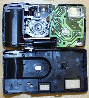
The little round silver circle near the center of this board is the power on button. Note it aligns with the power button on the front of the camera.
The bulb in the housing has 3 leads. An anode and cathode lead are the power leads and a trigger lead which goes to a coating on the outside of the glass tube.
Enter the crappy cell phone pictures... No switch in sight (At the risk of sounding haughty, I probably would have identified what was described as a switch). I took a few flash pictures with the camera before dismantling, and found that it is indeed necessary to hold down the charge button until the LED begins to flash and the whine stops increasing in frequency.
Posted: Tue May 10, 2011 9:03 pm
by mark.f
This is the trigger switch. Not quite sure of the original question but I hope this helps...
Posted: Tue May 10, 2011 9:16 pm
by Zeus
I suggest putting a transformer in parallel with the flash bulb, then use the trigger terminals to trigger it(duh).
Also put a SPST at the charging switch, that'll make charging it easier than holding down the charge switch.
Posted: Tue May 10, 2011 11:08 pm
by Hotwired
For various reasons I have a small database of flash circuit pictures and in fact the actual circuits too.
Here's the one you have.
Blue is the charging button. I can never really be bothered with it so I solder those as permanently connected and put a switch on the battery instead.
Red is the trigger switch ofc, you flip that to trigger the flash tube.
Yellow is the flash. Three connections should be there. One for each end of the bulb plus either a wire or a thin metal strip which ends on the metal reflector around the bulb. That thin wire or strip is the trigger wire.
I have no idea how you want to play with it but if you want to use the circuit as is with no further components then you need to:
Discard flash tube. Get the two connections from each end of the tube and set up two sparking points about 3mm apart.
Get the trigger wire as close as possible to this gap, I like to make a tiny loop and rig it just around the gap between the two sparking points.
Connect power to the circuit - the capacitor will automatically charge now because if you followed my advice the charging button is fixed "on".
Close the trigger switch when capacitor is fully charged.
The trigger wire will now ionise the gap between the two sparking points which will arc in a powerful spark as the capacitor discharges.
This is my example rig which has the two sparking points held apart and the trigger wire looped around the gap, I linked up a small push button switch to the trigger switch and I'm pressing it when the capacitor is charged (red LED glowing on the circuit I'm demoing with).
[youtube][/youtube]
Posted: Wed May 11, 2011 12:09 am
by Technician1002
Nice job getting the trigger to initiate an arc. I have not seen that done with air before except when a tesla coil was too close to powerlines outdoors. It initiated an arc on the power lines.
Posted: Wed May 11, 2011 10:25 am
by saefroch
So I want the end of the trigger wire about centered in the probable path of the arc?
Posted: Wed May 11, 2011 11:12 am
by al-xg
I've done this before using just a simple straight electrode for the trigger. They need to be very close. Having long parallel electrodes is a good idea to give a larger range of sparking points, as they do get damaged when discharging.
Does the loop work a lot better than just the straight electrode ?
I must admit it was quite fiddly to get set up right with just the straight ones.
The simpler two electrode setup (between trigger and main capacitor pin) is good for doing multiple spark gaps though.
Posted: Wed May 11, 2011 11:52 am
by Hotwired
saefroch wrote:So I want the end of the trigger wire about centered in the probable path of the arc?
Yes.
The way it works is the two flash bulb wires have a difference of 300V between them.
However 300V can't jump ~3mm in air.
When you press the trigger switch the third wire suddenly pulses to a few thousand volts, that ionises the air around it, making the air a lot more conductive and letting the 300v jump across.
It doesn't ionise the air very far away from itself so it does need to be close.
Technician1002 wrote:Nice job getting the trigger to initiate an arc. I have not seen that done with air before except when a tesla coil was too close to powerlines outdoors. It initiated an arc on the power lines.
That doesn't sound entirely healthy, playing with a tesla coil under powerlines.
Posted: Wed May 11, 2011 12:47 pm
by saefroch
Hotwired wrote:Yes.
Thanks, all I really needed
I have a 101-level understanding of E&M, but I've never encountered a switching mechanism like is described, so I wasn't quite sure how it worked. Soon as I have a switch I'll test the setup, then hook up another identical capacitor in parallel and see what I can do.


