

Taking some serious inspiration from SB15's TBMA2.0 and Mr.C's Mjollnir, I have been working on a hybrid of my own. I have been using mainly the pictures in SB15's thread to go on, and have learned a lot about hybrids and pistons from the forums here, and I feel like I am ready to tackle the challenge.
So far, I have the gun design made from 2 inch galvanized steel pipe fittings rated at 150 psi, although I have been assured that the yield strength is much higher. A barrel made from 1.5 inch EMT conduit, and am planning to use the 30kV ignition system from ultimatespudgun.com along with a spark plug. Anyway, I just wanted to show you guys what I have so far so you can point out anything I am doing wrong, or to potentially help others who wish to build a similar cannon. Anyway, here are some pics:
First is the barrel, 1.5inch EMT conduit x 48 inches long:

I was unable to get the pipe threaded, but found that a 2inchx1.5inch reducer fit VERY snugly over the pipe, the threads even grabbed it a bit. So I filled the fitting with JB Weld and rammed it onto the end of the pipe essentially. I will be sure to aim far away from anything destructible in case I end up with a flying pipe for the first shot. I plan on actually welding it later. The pipe passes through the cam lock fitting perfectly:

Next, I have started on the piston valve:

Here is the vent port at the back, closed:

And open:

Here are some pictures of the 1.5 inch nipple inside the reduction fitting which acts as a 'hard' stop for the piston, to keep the o-rings from slipping out of the 2 inch nipple. I think I will JB weld this in there as well. I now need to figure out what to use as a bumper and where to pit it. I am thinking I will drill holes around the circumference of the 1.5 inch nipple to allow more airflow, and use half a tennis ball wedged in the reducer for a bumper. Any suggestions?:


Here is a picture of how the piston seals inside the 2 inch nipple. I haven't had a chance to pressure test it yet, but from what I can tell, the double o-rings will seal well:

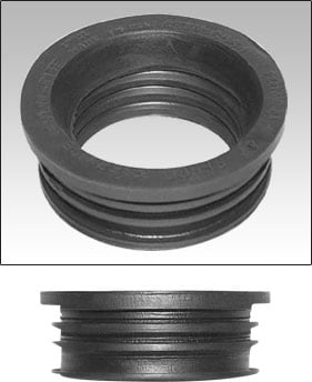
Here is the piston so far. It is a floating O-ring design, and fits inside the 2 inch nipple. I am planning for an actuation of around 1.5 inches, so the piston has full movement from one end of the nipple to the other. I plan to JB Weld the nuts in place to seal the piston once I have the distances fine tuned, and then trim the ends of the rods. I think I will also make a handle for the end of the port to help get the piston seated before filling the pilot with air pressure. Also, a gratuitous amount of JB Weld was used to attach the 5/16" inch rod to the 1/2" coupling nut. I could not find any reducing nuts or bushings ANYWHERE. This seems like an acceptable alternative (correct me if I'm wrong):

Finally, here is the sealing face. It is a 1.5 inch nipple JB Welded to the inside of a 2x1.5 inch bushing. It protrudes into the tee, which the rubber on the piston seals against:

If any of you experienced builders can point out any problems I might have, that would be great. Thanks for looking!
Finally, here is a shot of the layout. I am planning on putting the meter and electronics on the right hand side to facilitate firing from the right hand shoulder. I will also be using my homemade pistol grip as a trigger for the igniter circuit:


I will have more progress in approximately a week when I am done finals and move home and have access to my Dad's shop and the drill press and pipewrenches, taps, etc. I'm a little bit limited in my basement here in the city.


