Camera flash ignition - my experience
Posted: Sat Nov 30, 2013 4:17 am
Hello fellow crazy people.
I know there has been posts on camera flash ignitions but I would like to share my experience. As you can guess my circuit board looked nothing like the one in the very good 'how to' here. Credit for the inspiration.
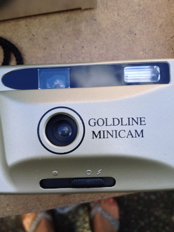
To start with I found a camera, a non disposable type.
After opening I searched and searched for the schematic. Think this was closest
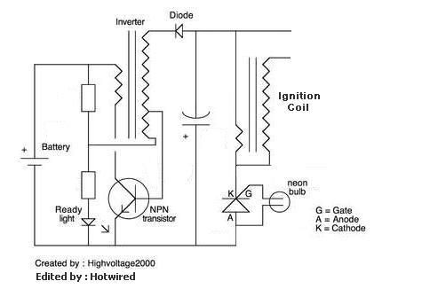
Regardless of how it's laid out, these are the parts required.
The main transformer - biggest in size. My camera also had a tiny flash inducing transformer. Not required
A transistor. This has 3 Legs and black in colour and is responsible for turning the dc from the battery to a pulsed form required by the transformer.
A diode. This is a black cylinder with a wire through the middle. This rectifies the pulsed form.
One or more resistors. Mine has one between power in and a feedback coil within the transformer. If you have more which could also include surface mount on the other side of the board, proceed with caution. If the resistor lies intermittent with the above list keep.
A capacitor - remove the supplied electrolytic taking note of its location and familiarising yourself with where you will fit the replacement when you cut the circuit board down. I started with one 0.1 micro farad PP capacitor but I've doubled that now.
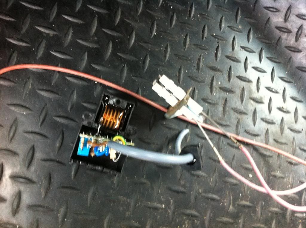
This shows a ignition from an old gas cooker I scavenged a spark gap from. Guessing they are 200 - 230v breakdown, ebay is another option. For better results try to find higher rated ones. This circuit works perfectly on 3v which is double the normal. Expect 500 - 600v if supplied with 3v
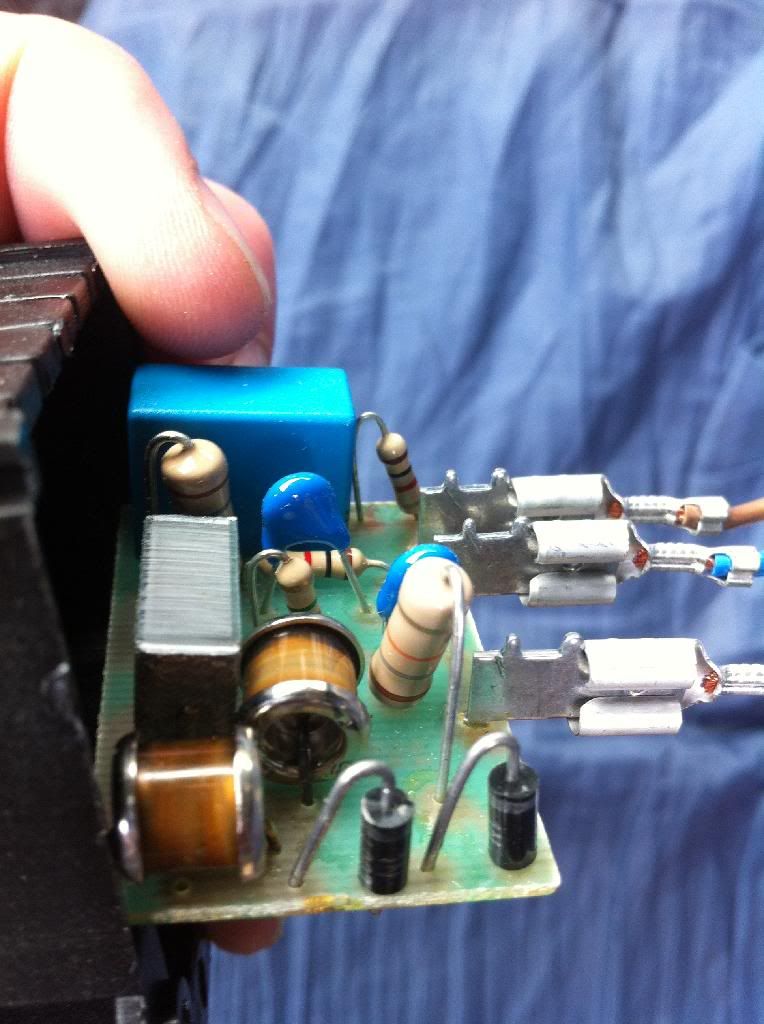
Then I also found a scrap boiler with electronic ignition. The coil is the only part required but platinum electrodes are worth keeping.
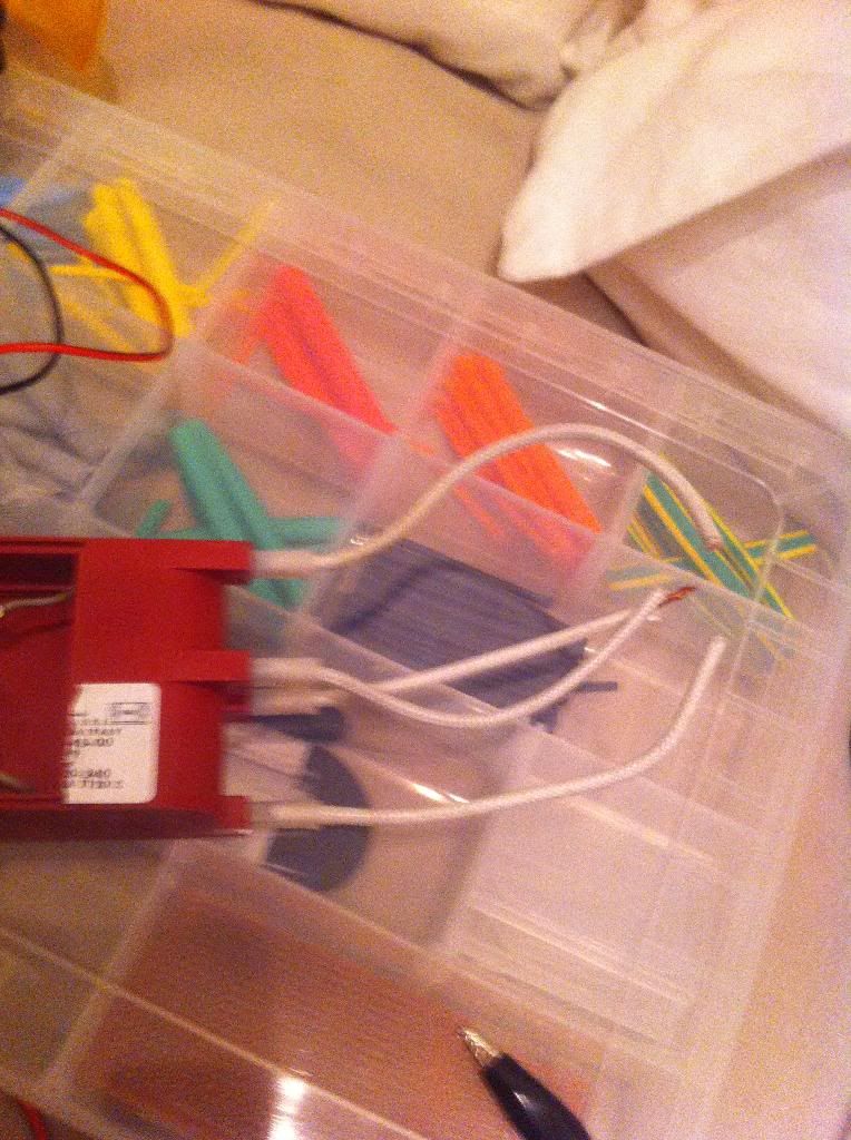
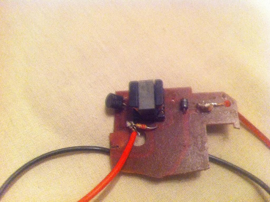
My camera circuit after the chop down. For reference power in is one side of the resistor. Power out is after the diode. Ground stays constant and daisy chains between parts.
I'm having problems with my photo bucket but I'll post a vid shortly.
I know there has been posts on camera flash ignitions but I would like to share my experience. As you can guess my circuit board looked nothing like the one in the very good 'how to' here. Credit for the inspiration.
To start with I found a camera, a non disposable type.

After opening I searched and searched for the schematic. Think this was closest

Regardless of how it's laid out, these are the parts required.
The main transformer - biggest in size. My camera also had a tiny flash inducing transformer. Not required
A transistor. This has 3 Legs and black in colour and is responsible for turning the dc from the battery to a pulsed form required by the transformer.
A diode. This is a black cylinder with a wire through the middle. This rectifies the pulsed form.
One or more resistors. Mine has one between power in and a feedback coil within the transformer. If you have more which could also include surface mount on the other side of the board, proceed with caution. If the resistor lies intermittent with the above list keep.
A capacitor - remove the supplied electrolytic taking note of its location and familiarising yourself with where you will fit the replacement when you cut the circuit board down. I started with one 0.1 micro farad PP capacitor but I've doubled that now.
This shows a ignition from an old gas cooker I scavenged a spark gap from. Guessing they are 200 - 230v breakdown, ebay is another option. For better results try to find higher rated ones. This circuit works perfectly on 3v which is double the normal. Expect 500 - 600v if supplied with 3v

Then I also found a scrap boiler with electronic ignition. The coil is the only part required but platinum electrodes are worth keeping.

My camera circuit after the chop down. For reference power in is one side of the resistor. Power out is after the diode. Ground stays constant and daisy chains between parts.

I'm having problems with my photo bucket but I'll post a vid shortly.
