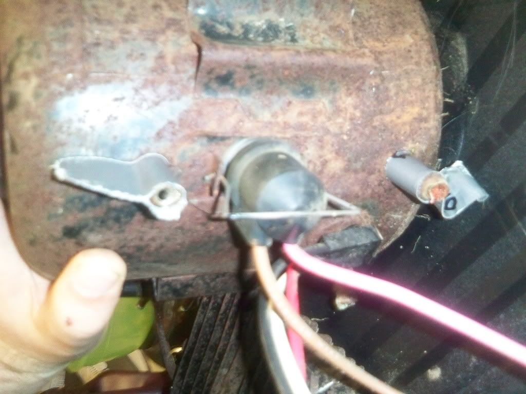
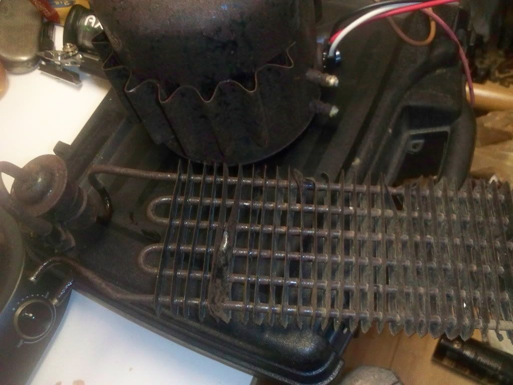
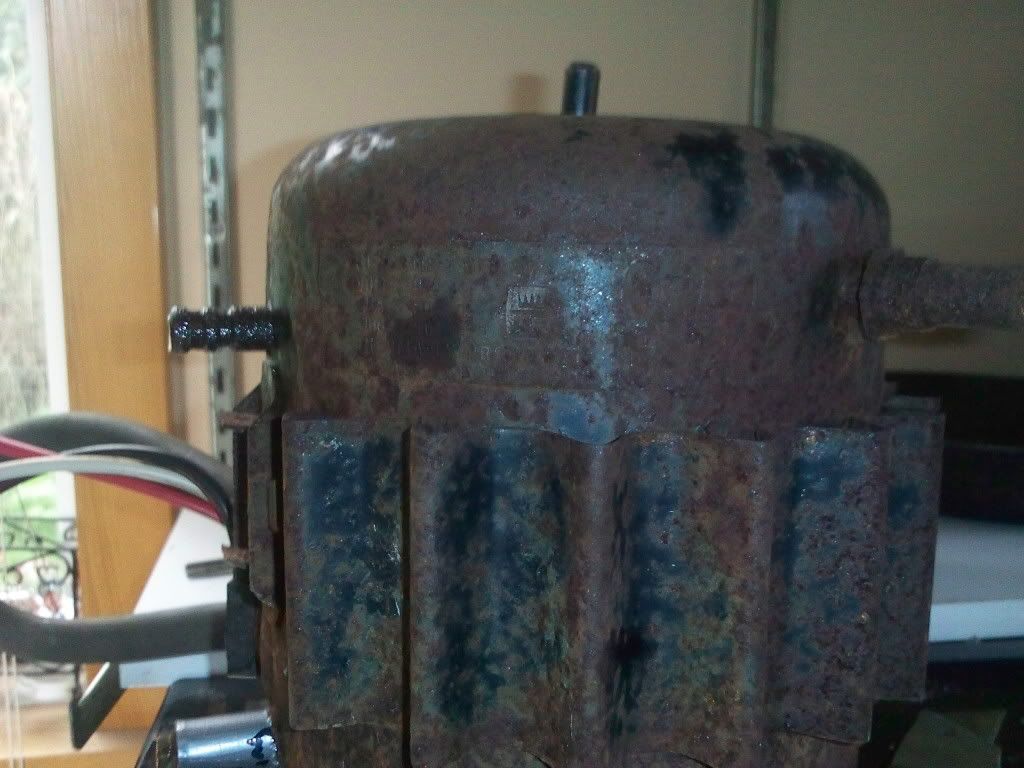
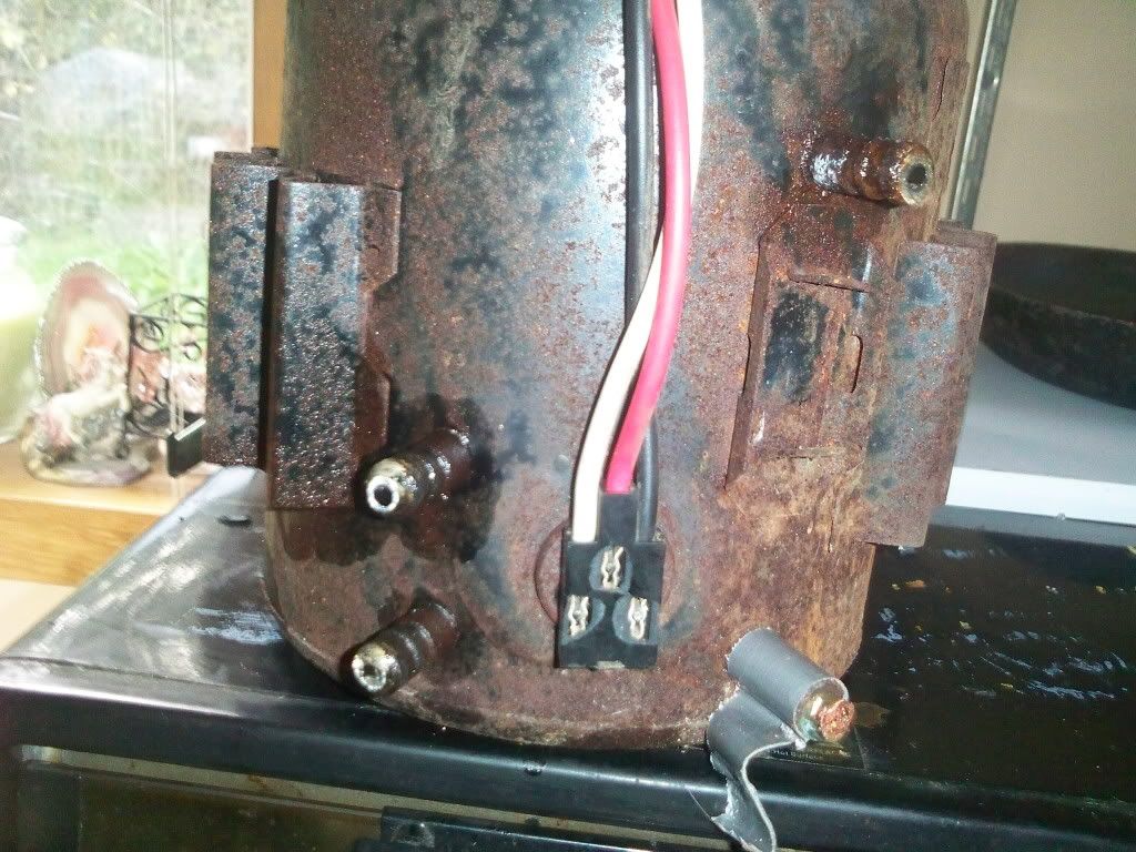
My compressor, 300 psi and more (..... much more :-D )

A place for general potato gun questions and discussions.
User avatar
POLAND_SPUD
Captain
Captain
Posts: 5402
Joined: Sat Oct 13, 2007 4:43 pm
Been thanked: 1 time

Thu Sep 10, 2009 3:16 pm

I've finished this

I used some strange material for it... don't ask what it is - I don't know :D

at first I though it doesn't work at all because the gun or anythign attached to the compressor was still 'spiting' with oil... but after half an hour of filing and venting the tank I could fill that the flow of oil stopped.. apparently there was a lot of oil inside the air-hose and the tank...
Attachments
FILE0047.jpg
FILE0046.jpg
FILE0045.jpg
Children are the future

unless we stop them now
User avatar
boyntonstu
Sergeant
Sergeant
Posts: 1039
Joined: Sun Jun 28, 2009 8:59 am

Thu Sep 17, 2009 2:19 pm

My non-dryer dryer?

Image

I cut it open expecting to find desiccant inside.

All I found was a screen.

I replaced the screen an hot glued an elbow on the chamber to prevent junk/ater from getting inside.

FWIW

BoyntonStu
User avatar
Technician1002
Captain
Captain
Posts: 5189
Joined: Sat Apr 04, 2009 11:10 am

Thu Sep 17, 2009 2:42 pm

boyntonstu wrote:My non-dryer dryer?

I cut it open expecting to find desiccant inside.

All I found was a screen.

I replaced the screen an hot glued an elbow on the chamber to prevent junk/ater from getting inside.

FWIW

BoyntonStu
On a refrigeration system the dryer is most often placed after the condenser so liquid flows through it right before the expansion valve or capillary tube so it catches any junk that may plug up the small orifice. The tank you cut on the compressor is either an oil separator or an accumulator.

An accumulator is used on some air conditioners to adjust the amount of freon in circulation. On cooler days the freon will operate at lower pressure, so less gas mass is used and the system may have too much liquid. It collects in the accumulator. On hot days the system pressure is higher which requires more freon, so the accumulator boils off the freon and provides the additional pressure required so the expansion valve doesn't run out of liquid. With the screen, it may just be an oil separator. An oil separator will have a 3rd tube connected to it to return oil to the crankcase. A filter dryer only has two tubes connected, an in and out.
User avatar
Northir
Specialist
Specialist
Posts: 123
Joined: Sun Sep 06, 2009 3:04 am

Wed Sep 30, 2009 2:24 am

im trying to build this with my fridge i cut the pipes off at the fitting of the compressor, since mine has little barbs that i can attach a 3/8" hose to, anyways, instead of 2 hoses this one has 4 outputs, 2 went into a heatsinc looking thing, i cut it off, and one went into the back heat sync and another into the top back of the fridge, when i cut that one it had a wire inside, i plug it in and it hums but i dont have any air flow, thoughts?
User avatar
Technician1002
Captain
Captain
Posts: 5189
Joined: Sat Apr 04, 2009 11:10 am

Wed Sep 30, 2009 3:52 am

Northir wrote:im trying to build this with my fridge i cut the pipes off at the fitting of the compressor, since mine has little barbs that i can attach a 3/8" hose to, anyways, instead of 2 hoses this one has 4 outputs, 2 went into a heatsinc looking thing, i cut it off, and one went into the back heat sync and another into the top back of the fridge, when i cut that one it had a wire inside, i plug it in and it hums but i dont have any air flow, thoughts?
You may find the pipe with the "Wire inside" is the expansion valve. In a refrigerator this is often a small tube between the condensor and evaporator. It meters high pressure liquid freon to the low pressure evaporator in the icebox where it boils and takes away heat.

The high pressure output from the compressor goes to the "heatsink" condensor coil on the back of the fridgerator. The tube leading from the evaporator is the low side tube that goes to the inlet of the compressor. Without a photo, I'm not sure where or what the other two tubes are. Some compressors have a crankcase loop to heat the crankcase to boil out freon that dissolves into oil to prevent it from foaming up when the compressor starts.

A photo showing all 4 tubes would be helpful. Many compressors have 3 tubes. An inlet, outlet and a process tube. The process tube is the tube used in manufacture to pump out the system and charge it with freon. The process tube is most often sealed shut after manufacture.
User avatar
Northir
Specialist
Specialist
Posts: 123
Joined: Sun Sep 06, 2009 3:04 am

Wed Sep 30, 2009 4:08 am

will have pictures any second, trying to get my phone to cooperate

Edit: here they are

Image

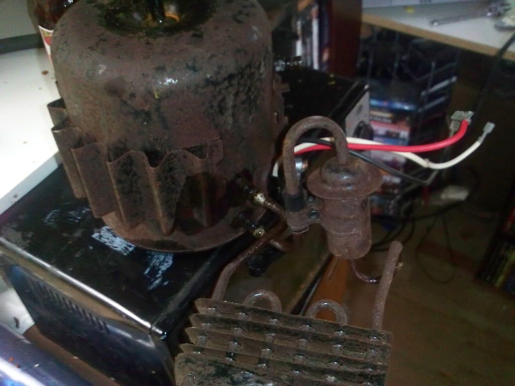
Left is the top, which led into the top of the coil on the back of the fridge, right is the bottom which had the wire in it, lead into the interior of the fridge

Image
can kinda see where this was connected on the compressor, this is what i figured was a heat sync
User avatar
POLAND_SPUD
Captain
Captain
Posts: 5402
Joined: Sat Oct 13, 2007 4:43 pm
Been thanked: 1 time

Wed Sep 30, 2009 6:27 am

hmmm now I am totally lost... :wink:

have you tested it before sealing one of the tubes ??

also could you take more pics ?? or find info who manufactured it or what model it is ??
Children are the future

unless we stop them now
User avatar
Northir
Specialist
Specialist
Posts: 123
Joined: Sun Sep 06, 2009 3:04 am

Wed Sep 30, 2009 4:34 pm

when i plug it in it hums and thats about it, it did the same with the "heat sync" attached, im starting to think this compressor is toast


heres some more images of the compressor,

Image
This one is the manufacture tag, ill try some photoshop in a sec to see if i can read it better

Image
the side showing all 4 connections and power


Image
and showing how the "Heat sync" was attached, i tipped it over for a second and oil spilled out so i think im going to reattach, or just seal it
User avatar
POLAND_SPUD
Captain
Captain
Posts: 5402
Joined: Sat Oct 13, 2007 4:43 pm
Been thanked: 1 time

Wed Sep 30, 2009 4:55 pm

where is the starting relay ??
Children are the future

unless we stop them now
User avatar
Technician1002
Captain
Captain
Posts: 5189
Joined: Sat Apr 04, 2009 11:10 am

Wed Sep 30, 2009 7:23 pm

Northir wrote:when i plug it in it hums and thats about it, it did the same with the "heat sync" attached, im starting to think this compressor is toast

and showing how the "Heat sync" was attached, i tipped it over for a second and oil spilled out so i think im going to reattach, or just seal it
I made some edits to your pics to show the connections. I also located a cut open view to show the crankcase cooling loop. The small "Heatsink" is for crankcase cooling and is the individually separated condenser tubing circuit mentioned in the photo with the cooling tube.

As to where the starting relay is located, it is located on the other end of the wires in this model with the start cap and maybe a run cap. The book where I found the cooling loop pic has more information.

I hope this helps.

Screen captures stolen from here;
http://books.google.com/books?id=Sbu_X1 ... q=&f=false
Attachments
One of several relay and capacitor start/run connection combinations.  Not all compressors have the start relay on the compressor.  Some don't use a start relay and only use a run and start capacitor.
One of several relay and capacitor start/run connection combinations. Not all compressors have the start relay on the compressor. Some don't use a start relay and only use a run and start capacitor.
Oil Cooler in the compressor
More info.  Photo rotated to match the other photos orientation.  It was confusing at first.
More info. Photo rotated to match the other photos orientation. It was confusing at first.
Cooling loop connections and locations of cut out.
User avatar
POLAND_SPUD
Captain
Captain
Posts: 5402
Joined: Sat Oct 13, 2007 4:43 pm
Been thanked: 1 time

Wed Sep 30, 2009 8:04 pm

wow that was pretty informative...


it seems he found a pretty cool fridge compressor... lol it has a ready made cooling system and that sort of radiator from corrugated steel thingy welded to the case... of course it would be great if it was in better condition but still that's a nice find


anyway we still don't know whether there is a starting cap or not (and in what condition it is)

if that's the case I suspect that it would be easier for him to buy a starting relay than try to replace the cap...
Children are the future

unless we stop them now
User avatar
Northir
Specialist
Specialist
Posts: 123
Joined: Sun Sep 06, 2009 3:04 am

Wed Sep 30, 2009 8:15 pm

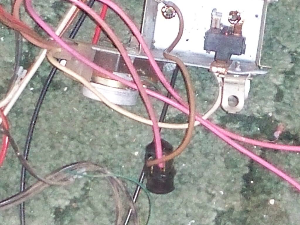
i had the entire fridge, just pulled the compressor, i think the starting system your reffering to is probably in this pile of crap
Image


theres a capacitor still outside, need to find that i assume, as well as a diagram of how to put it all back together, also sounds like i need to reattach the cooling loop,
User avatar
Technician1002
Captain
Captain
Posts: 5189
Joined: Sat Apr 04, 2009 11:10 am

Wed Sep 30, 2009 9:17 pm

Northir wrote:i had the entire fridge, just pulled the compressor, i think the starting system your reffering to is probably in this pile of crap

theres a capacitor still outside, need to find that i assume, as well as a diagram of how to put it all back together, also sounds like i need to reattach the cooling loop,
You don't need to reattach the cooling loop. The fins work just fine. The cooling loop is to keep the compressor cool when running 24 X 7. Intermittant use should be no problem. We use lower inlet pressure. We don't use freon so you won't get much benefit running just a little air through the loop. The fins on the case will keep it cool just fine.

Without the starting stuff, it won't start. It may hum, but it won't rotate and start pumping. You need to see if you can properly connect the starting cap, start relay, overload, etc. I hope you made a diagram before disassembly. The book in the link may provide your diagram. It would pay to examine the fridge to see if it still has a wiring diagram attached. Some do.
Attachments
Components identified.
User avatar
Northir
Specialist
Specialist
Posts: 123
Joined: Sun Sep 06, 2009 3:04 am

Thu Oct 01, 2009 2:48 am

im starting to remember how it went together for the most part, i need to go find that capacitor me thinks, i know that the red(may be green) wire coming off the unit goes to the capacitor then to my starting relay, i remember this caus of the connector that is on the wire, and then the capacitor goes to the broken connector on the relay, not sure which is + and which is - though, and theres 2 #s next to the other 2 connectors, "1" which is the bottom of the coil, and "5" which ends the coil on the top


EDIT: i sanded the tag a bit, found some #s, i googled all of them and couldnt find anything
Also i think i forgot to tell ya thanks a ton for the help in all areas of my cannoning
R1-23nb
1137872
J19A5
User avatar
POLAND_SPUD
Captain
Captain
Posts: 5402
Joined: Sat Oct 13, 2007 4:43 pm
Been thanked: 1 time

Thu Oct 01, 2009 6:59 am

couldn't he just buy a brand new starting relay??

like this one -> http://www.spudfiles.com/forums/my-comp ... t,105.html

it attaches directly to the compressor and has an in-built overload protection... that would simplify wiring a lot
Children are the future

unless we stop them now
Post Reply